SITE SURVEY
2.1.2 Alignment
The following points must be considered while
selecting an alignment for the gravity ropeway:
A) Profile
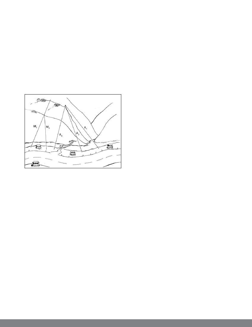
As far as possible, the ropeway line should
intersect the contour lines at right angles. If
the cross slope is unavoidable, the line must
be on the lower part of the cross slope (refer
to the attached schematic diagram).
Figure 6
A= Single span ropeway
M = Multi span ropeway
A1- Preferred alignment
A2 - Less preferred (ok only in unavoidable
condition)
A3 - Not preferred
M1= Correct alignment for multi span ropeway
M2 = Wrong alignment for multi span ropeway
Maximum gradient of the rope shall not exceed
45 degrees at the highest possible loading
conditions.
In a multi span ropeway, the ropeway alignment
should be in a straight line in plan. However
in special cases, deflection up to two per cent
per support/tower may be provided where the
support/towers are located in a very gentle arc
having minimum radius of 5000 metres.
The position of the lower station is usually
selected in the neighbourhood of a road or
market centre. Similarly, the upper station is
preferred on a suitable plateau near the hill
top with close vicinity to villages.
B) Clearance
One of the main difficulties in planning the
ropeway layout along its alignment is to ensure
suitable clearance between the base of the trolleys
and the ground level or the structure above the
ground.
The minimum clearance between the ground
and the base of the trolley while moving above
the ground shall not be less than five metres
even in the most unfavourable operating
conditions.
Wherever the ropeway passes over the forests,
a minimum clearance of 7.5 metres should
be maintained on either side of the route.
C) Crossing
The alignment of the gravity ropeway should
maintain suitable lateral clearance with all
possible structures that can be affected by
installation of ropeway such as settlements,
electric transmission lines, trails and roads,
bridges, cultivated land and other service
infrastructures. This requirement is necessary to
avoid any risk of accidents like objects falling
from the moving trolleys and breakage of wire
rope. If the crossing is unavoidable, proper risk
assessment should be carried out and appropriate
safety measures should be guaranteed during its
installation and operation.
2.1.3 Site geology and bank stability
It is important to locate the gravity ropeway
stations on visibly stable and flat land. The
areas exposed to the dangers of natural forces
(avalanches, landslide, rock fall and storms)
shall be avoided as far as possible. If the
danger is unavoidable, suitable protection
measures need to be taken.
9